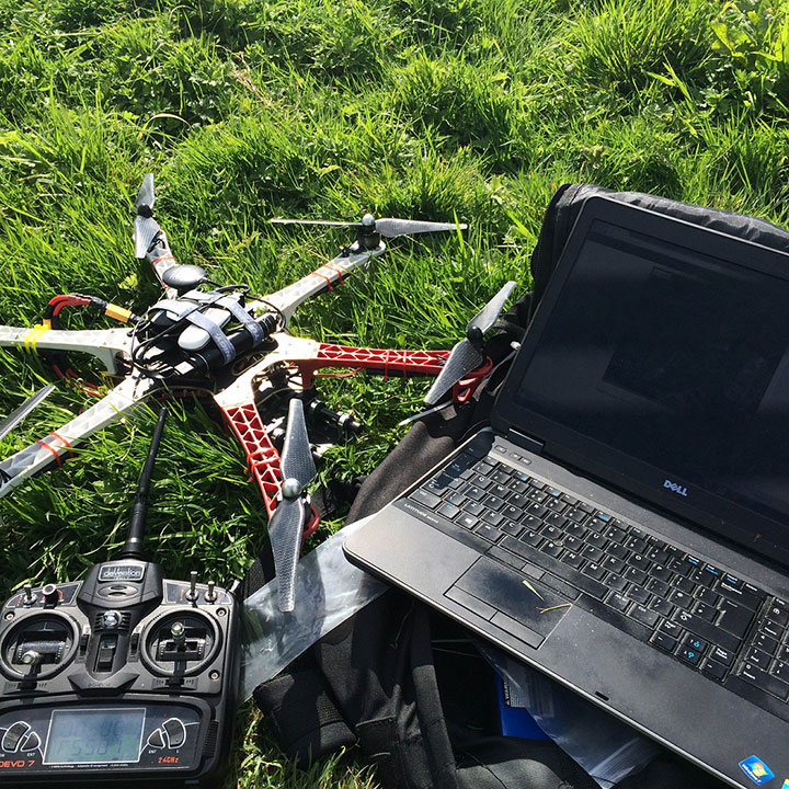
This blog, as the name implies, discusses how I went about designing and building our initial Wi-Fi mapping drone capability (and you can too, hopefully).

Before we begin, a brief disclaimer: we sought legal advice and complied with relevant laws. Before you embark on such a project, make sure you are aware of relevant laws in your country.
Cue A-Team building music
As with any good project, I started out with requirements, as I had quite a few things to think about, namely:
- Budget
- Size, and how it affects transportation
- How long will it stay active for (modes and battery efficiency)?
- Can it carry a payload?
- How is it controlled (automatic or manual)?
- Weight restrictions
- Law – see the UK’s Civil Aviation Authority and Unmanned Aircraft and Aircraft Systems
Then I had number of further considerations and requirements when building the mapping tool that would be carried by the drone:
- Budget
- Battery consumption
- Weight
- General processer usage
- How to attach it safely to the drone?
- How will the Raspberry Pi speak to the base station?
- How can I get the location of a wireless network?
The hardware shopping list to build the system is:
- Drone(land/air/water)
- GPS module/ USB GPS
- 3G/4G USB/module
- Raspberry Pi (tested with Pi 1B and P2)
- Wireless network adaptor packet injection
The required software is surprisingly sparse for the mapping tool:
- Linux (Raspbian).
- Python and associated libraries.
- Virtual private server
In order to understand how to map, I needed to research and understand how NMEA 0183 sentences worked, as this knowledge helped understand the Python library pynmea2. For plotting GPS information there is a great write-up on NMEA.
Researching the 802.11 OSI layers and understanding packet headers for the Python library scapy was also needed in order to support the mapping.
So how was it implemented?
At its core there are a number of boot-up scripts on the drone-carried Raspberry Pi. The first of these scripts starts two screen sessions; the first session sets the wireless interface into monitor mode, and the script then spawns a new process so the network interface can channel hop through 1-14.
In the second screen session another script (written in Python) creates a third process to read NMEA sentences from the GPS interface to detect how many satellites are in view. This script then collects the current latitude and longitude. This core logic uses Python’s Scapy library to read packets from the network interface, specifically looking for available access points in range. If the main script detects that there are not enough satellites in view when it sees a new access point it will not plot them. However if it detects that there are more than six satellites in view, it will then write the network information, including BSSID and GPS locations that the Wi-Fi access point was seen at, to a temporary cache file for later processing .
Another Python script then attempts to read the temporary cache directory every five seconds, to detect if the first script has written any networks. If the first script has written networks, the second script will connect to the remote virtual server’s MySQL database and replace the data in the database. The reason replacement is being used is that networks may get changed, so if the mapping tool goes past the network more than one time it can update the information in the database.
The final script that is run on the device is a cron job that will check for an SSH process. If an SSH process is not found, the script will create a reverse SSH connection to the remote cloud mapping server for remote administration (don’t want our drone payload being hacked).
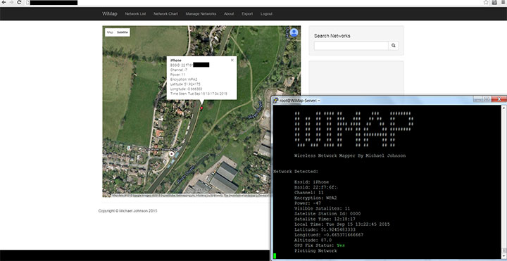
The remote server’s web interface currently includes:
- Google map with colour corresponded to authentication types RED/WPA ORANGE/WEP OPN/GREEN.
- Options to update, add, and remove network information.
- A pie chart of the gathered networks with statistics.
- Export networks in CSV format.

Published date: 21 September 2015
Written by: Michael Johnson
